Left to My Own Devices: Building a Class D Amplifier
Introduction
Kit
Parts
Case
Labeling the Case
Building It
References
In 2020 I decided to get back into hifi after a decade hiatus,
and I needed a new amp since I had sold my previous Class AB amplifier.
I am partial to amps designed by ATI (Outlaw, Monoprice, etc),
but the Class AB amp I really wanted was back-ordered for many months because everybody else sitting at home
during COVID had the same idea. My backup plan was to assemble a Class D amp from a DIY kit
which was readily available despite never having heard or owned one.
I wanted my amp to be made in the U.S.A., so that ruled out the typical solution of European
circuit boards crammed into a Chinese case. After scouring many forums, I decided to try
the 4-channel SDS-1000 kit from Tom Ross at Class D Audio.
I have assembled speakers from kits, and I know how to solder, but I had never assembled
an amp before. This article is written from a newbie’s perspective to help others who may
have the same questions as I did along my journey.
If you are an experienced amp builder, you probably won't get much out of this.

Meme stolen from audiocircle.com
Here is what comes in the SDS-1000 kit:
- Two 2-channel SDS-250 boards.
- Toroidal transformer. This is the AnTec AN-5435 and weighs over 11 pounds. It is drop-shipped separately from New Jersey.
- Power supply board. The kit comes with a brown "twin" board that powers both modules. This is different than the red board you see in forum pictures that powers a single SDS-250 module.
- Standoffs and screws to mount the above components. The standoffs are nice because they are threaded on both ends so you don't have buy a pop rivet or thread boring tool to mount the boards – you can just drill holes in the bottom of the case.
- 4 potentiometers. The pots allow you to adjust the attenuation level. Some people say you should determine the correct level and then hardwire a resistor inside the case for better sound quality instead of using a pot, but I'm not that sophisticated. 1/4" shaft diameter; 9/16" threaded diameter.
This kit is designed for people who know how to build amplifiers. The instructions consist of photos of an example assembly with arrow callouts to the various ports on the boards.
You won't see step-by-step instructions like, "Step 1. Solder blue lead X to port Y".
I had to do a lot of research in audio forums to understand how to assemble it.
The kit doesn’t contain everything you need, so you still need to buy parts.
I bought mine from
Parts Express
plus my
local electronics surplus store, but there are
many options.
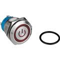
- Power switch.
PE part number 060-944. I like this illuminated one because it takes 120V directly from the IEC power jack instead of requiring a relay. 3/4" hole.
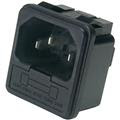
- Power jack.
PE part number 090-443. It contains an integrated fuse box, but you have to supply your own 5A or 6A GMA fuse. You can solder or use 3/16" quick disconnects. Cutout dimensions: 27 mm (W) x 31.5 mm (H).
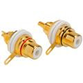
- RCA jacks.
PE part number 091-1120. The center post is wired to + on the amp board, and the tab is wired to G (the - is only used for balanced sources). 3/8" hole is the diameter of the nylon washer's flange that isolates the jack from the metal case. 12mm nut.
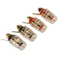
- Binding posts.
PE part number 320-3375. The "mini" in "mini-RCA" refers to the inside dimension: these are designed for amps and not speaker cabinets which could be 1" deep MDF. 1/4" mounting hole. The comments section is correct: the diameter of the knob really is 14mm.
- 3-Pin JST connectors. Purchased from my local electronics store. These connect the pots to the boards.
- Rubber feet. PE part number 260-7513. I attached these to my case with 1/2" #6-32 screws.
- Pot knobs. Purchased from my local electronics store.
- Hook-up wire. Purchased from my local electronics store. Class D Audio says to use 16 AWG for power and speaker, and 20 AWG for inputs. Using solid wire for power is
not recommended because it can easily break.
I spent a lot of time thinking about what case to use.
Many of the foreign specialty cases for Class D amps are for the European boards, and their YouTube
installation videos looked tedious.
I decided on a vented aluminum case, model 20-16164N, from
Pi Metal (née Par-Metal) in New Jersey.
Their primary online presence is eBay.
Honestly, their product photos do not look great, but the case looks good in person, and it feels well made.
Their 20- product line is designed for amplifiers by having a front face that is thicker than the other sides.
The case footprint is 16"W x 16"D x 4"H which I was afraid would be too big, but it turned out to be just right. I read in forums that having extra room inside the case is nice, and now I believe it.
The case does not come with rubber feet, but there are holes pre-drilled in the bottom corners for them.
At first I considered using a label maker on the rear of the case and not worrying about it.
After all, I'm the only person who will look there, and I'll forget about it after initial setup.
Then I decided I wanted to elevate the design a bit.
But how to create and transfer an image to metal?
I knew of a technique of using acetone to transfer laser printer images to copper circuit boards, but I didn't know if it would work on other metals.
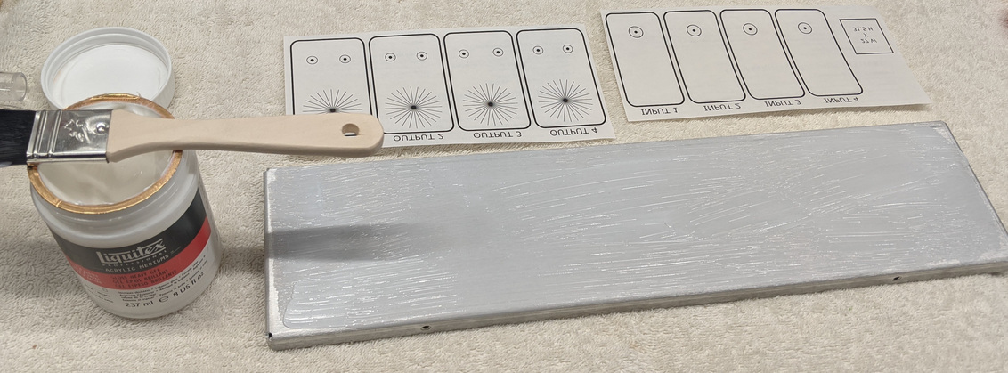
It turns out you can use an acrylic gel called
Liquitex
to transfer laser printer toner from waxy paper to metal
(you may want to watch that previous link just for the entertainment value alone).
What software can you use to create the image? You can use whatever you like such as Gimp, Photoshop, PowerPoint, etc, but I wanted something that could give me automatic alignment, the ability to create star patterns for knob adjustment, and holes with exact sizes in inches or millimeters.
Then I discovered Inkscape from this article. I had never heard of this vector-based graphics program before, and I love it. It feels similar to Gimp, and I found it very easy to use.
My .svg vector file for a 16" wide panel spanned more than one 8.5x11" piece of paper, so I used Adobe Acrobat Reader's poster option to split it across multiple sheets of paper.
I left space for future XLR input jacks since I don't use balanced inputs in my equipment today.
Applying the Liquitex Gloss Heavy Gel Medium
Despite a successful trial run on the interior of the case (you will see it in the pictures below), the end result wasn't as good as I wanted.
I suppose more practice with different pressure, using a hand roller, waiting longer than 2 or 3 hours, or
varying the amount of gel applied could make a difference. But I consider it good enough, and having neatly aligned drill holes plus an exact cutout for the power jack made it worth the effort.
Not great, but good enough
The look is "weathered" or "rustic", if you will.
The first step was laying out the boards on the bottom plate to mark the holes to drill.
I wanted the transformer to be as close to the center line as possible for even weight distribution.
Initial layout
I found the following image helpful for mounting the toroid since I didn't know the official way to mount it.
My 5/16" bolt is mounted upside down compared to this image so that it comes up from the bottom.
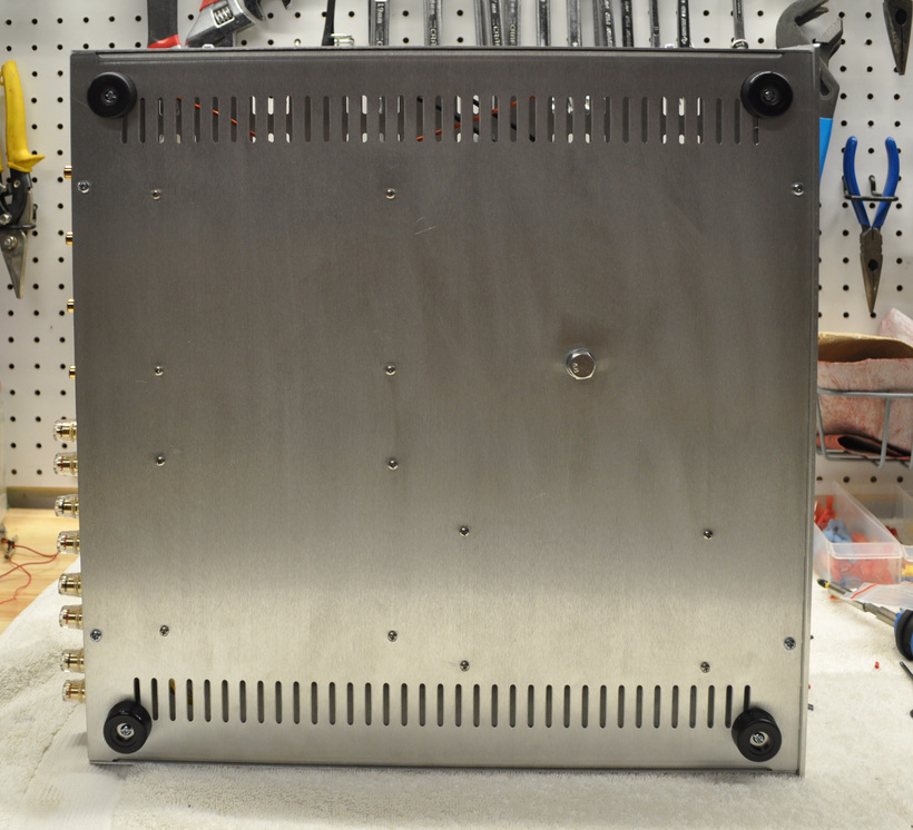
I drilled the holes with a drill press.
With the exception of the toroid bolt, the bottom holes are 7/64" (or 1/8" if you want some leeway).
Bottom view
The first thing I soldered was the power supply. The brown "twin" rectifier board does not use barrier terminals like its predecessors, so after consulting with Class D Audio, I soldered the power leads directly to the board.
"Helping hands" are useful for soldering
I decided to put the power button on the left side since all my other components have it there.
It seems like a common design pattern to have both the power button and jack on the left side of the case as you look at it from the front.
One "normally open" contact goes to 120V, and the other one goes to the toroid. The remaining + and - contacts are for the LED; one goes to switched power, and the other returns to neutral.
Power button
The potentiometers had protrusions on them that prevented me from mounting them flat against the back panel.
I didn't know what they were.
It turns out those little tabs are an
anti-rotation device.
Not wanting to cut them off,
I installed a couple of toothed lock washers on the shaft that added up to the height of the tab.
Those washers – combined with the fact my 9/16" drill bit cut shoddy holes that required me to thread the shafts through them – resulted in the pots being securely mounted. JST connectors connect the pots to the boards.
Potentiometers
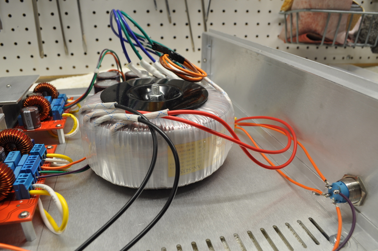
After hooking everything up, I decided to give it a listen. And I was crestfallen upon hearing a dreaded 60Hz hum coming from the speakers. At first I thought it was a ground loop. I tried different interconnects to no avail. More experimentation revealed that the hum was only present when I used channels on one amplifier board but not the other.
I discovered the cause was the output leads were too close to the 120V leads on the transformer. Take a closer look at one of the photos above:
Hum caused by output leads too close to 120V
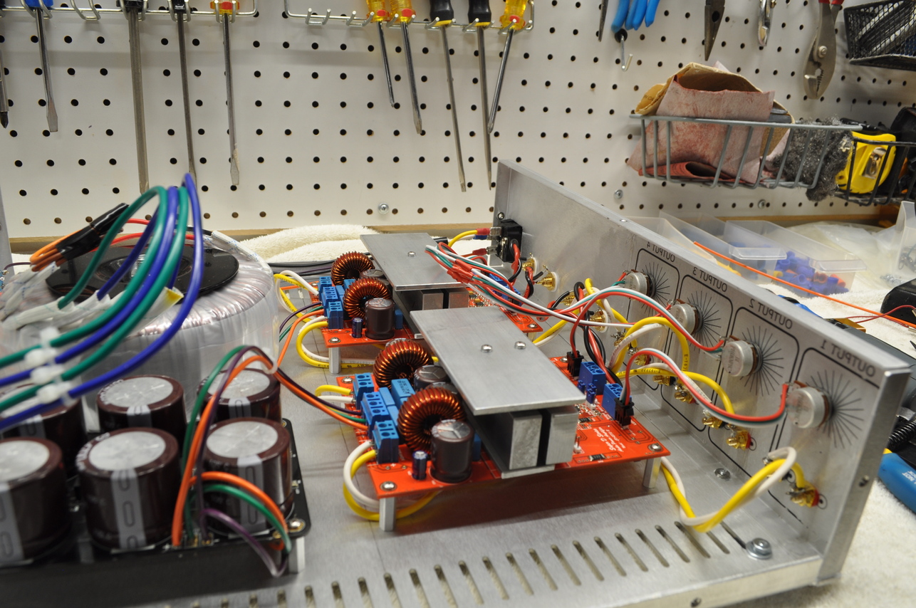
After rerouting the output leads underneath the amp boards, the hum went away!
Rerouted outputs
The general advice in forums is to keep the output leads away from AC lines and the input leads as short as possible.
Inputs and IEC jack
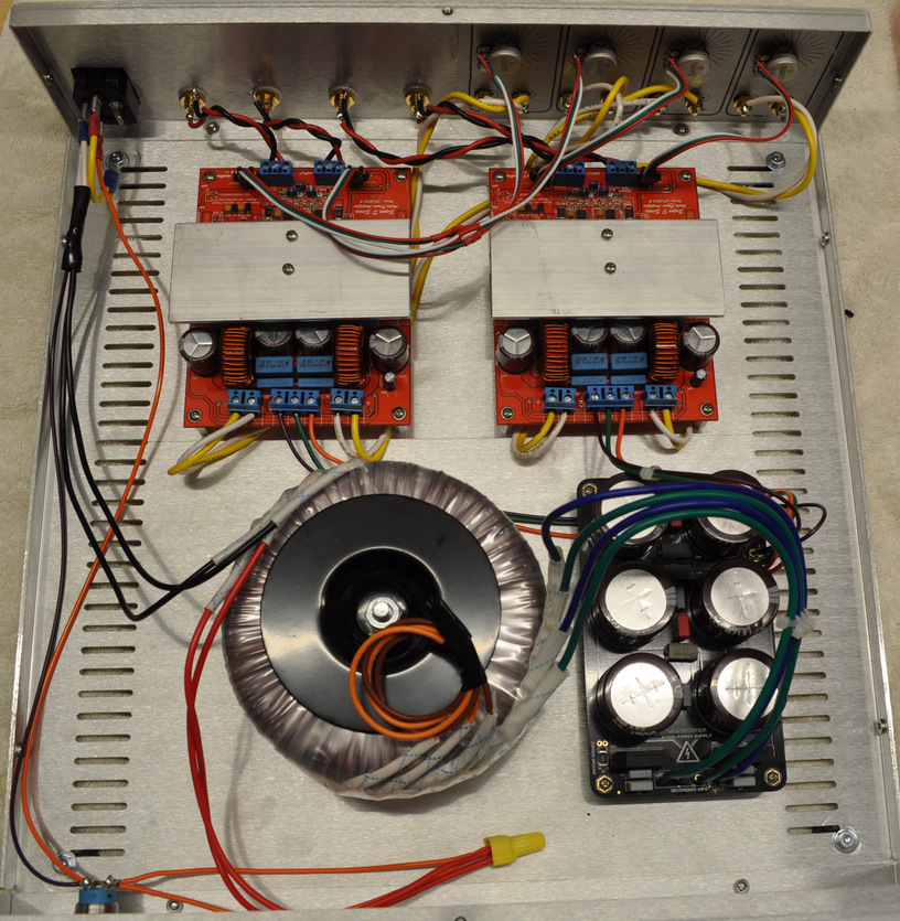
Final wiring configuration
Rear view
Front view
Total cost: about half the price of a comparable Class AB amp.
Much of the following material is a decade old but has stood the test of time.